Alarm Display: A.042 Alarm Name: Multiple Parameter Combinations Exceeding Set Range. Situation at Alarm Occurrence: Occurred when the power was turned ON again after changing electronic gear ratio (Pn20E/Pn210) or changing the motor to the one with different number of encoder pulses. Cause: Speed of program JOB operation (Fn004) is out of range by changing […]
Category Archives: SMT Machines MRO

10
Jul
Jul
Alarm Display: A.041 Alarm Name: Dividing Pulse Output Setting Error Situation at Alarm Occurrence: Occurred when the control power supply was turned ON. Cause:The PC dividing pulse set for Pn212 is out of the setting range and does not satisfy the setting conditions. Corrective Actions:Set Pn212 to the correct value.
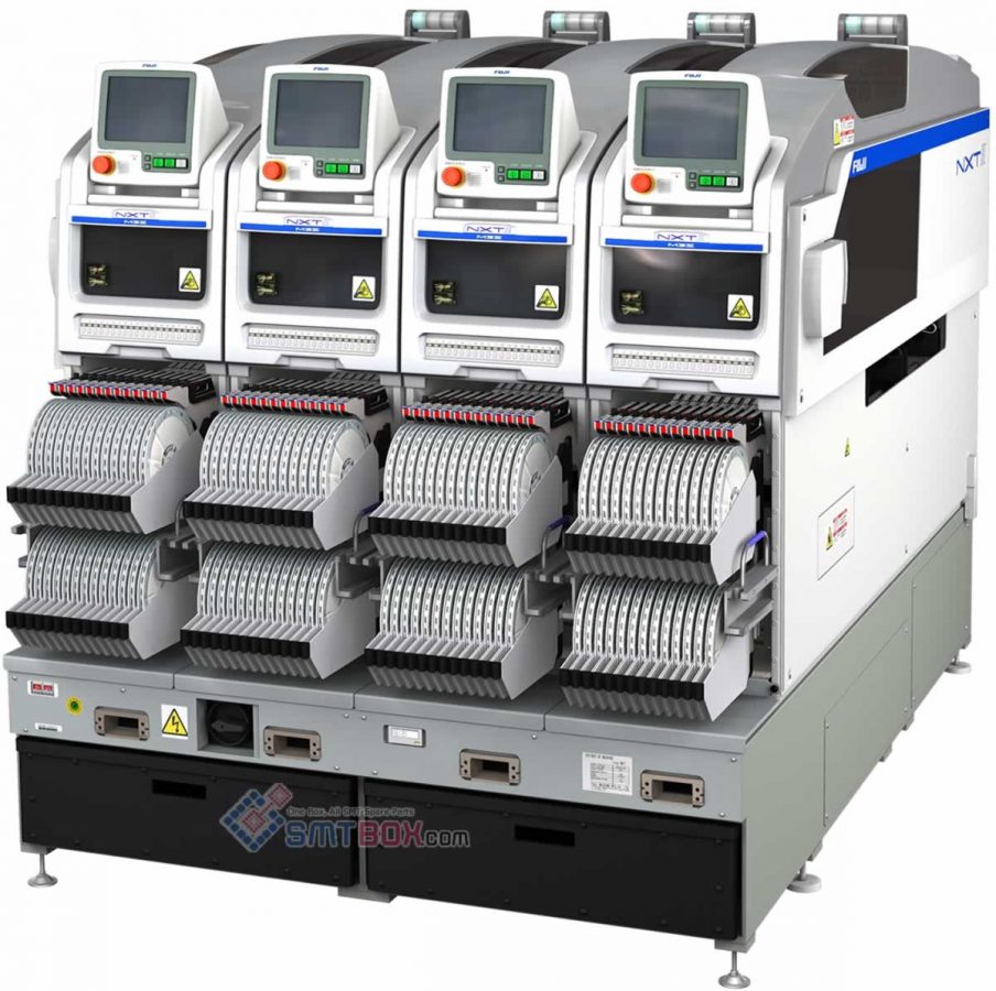
#1 P/N: 630 154 4595 | Frame #2 P/N: 630 130 8302 | Assy Cover #3 P/N: 630 130 8319 | Cover(D) #4 P/N: 630 130 8296 | Plate #6 P/N: 630 128 9021 | Sensor Photo B01#Ee-Spy424-P1 #7 P/N: 411 039 2604 | Scr Pan 2X6 #8 P/N: 411 141 2509 | Washer Spr […]
08
Jul
Jul
The method for assigning a fixed alternate feeder for an NXT is different than other machines. For other machines an alternate feeder loop has to be created while for the NXT an extra feeder with the part is just added to the module and the NXT will automatically use this extra feeder as an alternate […]
05
Jul
Jul
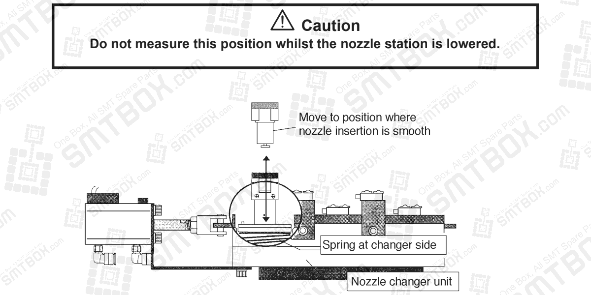
For nozzle station only 1. Press [SET] – [POSITION] – [Module #] – [NOZZLE] – [STATION] – [UP]. 2. Bring the head to a position where the nozzle holder fits smoothly into a nozzle in the nozzle changer. 3. Press [SET] – [PROPER] – [ID CODE] – [Module #] – [NOZZLE SELECT] – [Xn/Yn] – […]

04
Jul
Jul
1. Install a 10 mm nozzle. 2. Align the nozzle center to the center of the parts eject box. 3. Press [SET] – [PROPER] – [ID CODE] – [Module #] – [ETC] – [EJECT POS] – [REJECT BOX] – [SET].

03
Jul
Jul
How to measure x-axis and y-axis proper data. Here is the description: The MFU origin position sets the pulse count the head moves to when picking parts from the feeder. 1. Install the device jig in D1 on the MFU. 2. Attach a nozzle jig to the nozzle holder. 3. Move the head to a […]
02
Jul
Jul
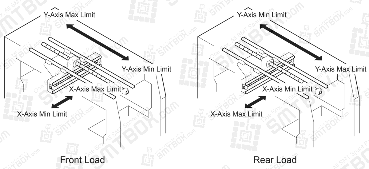
What is the Max and Min Limit Positions X/Y? Description: The Max/Min limit positions are used to stop the axes from hitting the stopper. During normal operation the machine will generate an error if a command to move outside these ranges is received, however when inching an error will be generated if the axis hits […]
01
Jul
Jul
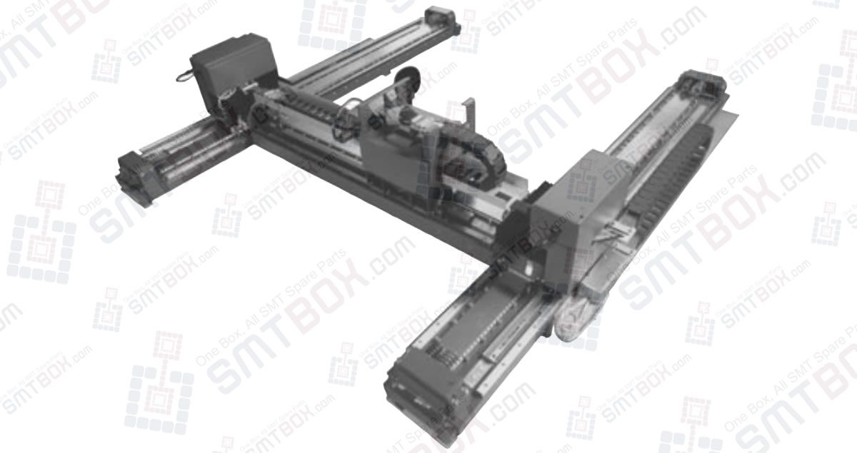
The H-Drive manipulator is a self-calibrating Cartesian robot with linear motors and encoders. The manipulator has two Y-axes and one X-axis, each with their own integrated controller and power stages. Special attention is given to the dynamic behaviour of the manipulator which is of great importance for the performance. Settling times are defined as the […]

26
Jun
Jun
Alarm Display: A.04A Alarm Name: Parameter Setting Error 2 Situation at Alarm Occurrence: Occurred when the control power supply was turned ON. Cause: Parameter is set out of range. Corrective Actions: Set the parameter within the specified range. Cause: The SERVOPACK EEPROM and the related circuit are faulty. Corrective Actions: Replace the SERVOPACK.