
The MVME162P4 uses a Zilog Z85230 serial port controller to implement the two serial communications interfaces. Each interface supports: 1. CTS, DCD, RTS, and DTR control signals 2. TXD and RXD transmit/receive data signals 3. TXC and RXC synchronous clock signals The Z85230 supports synchronous (SDLC/HDLC) and asynchronous protocols. The MVME162P4 hardware supports asynchronous serial… Continue reading about Serial Connections on Motorola MVME162P4 VME Embedded Controller
Category Archives: SMT Machines MRO
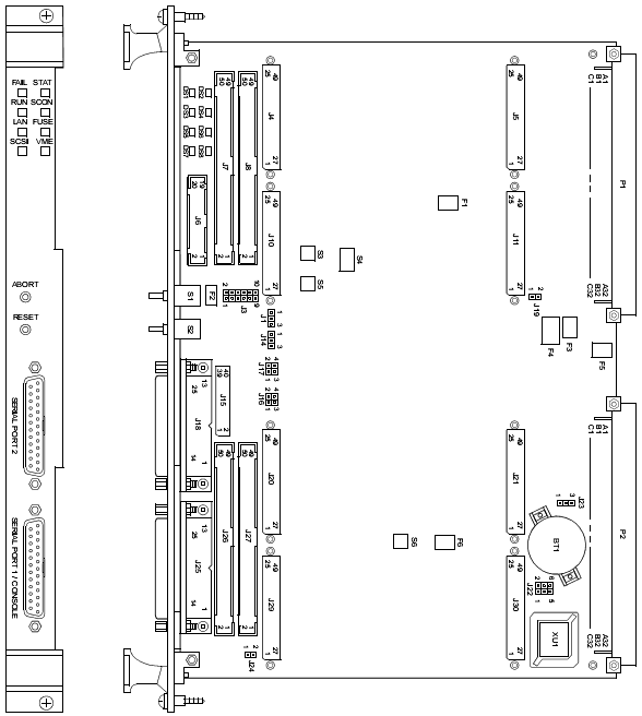
This section covers: A. Installation of IndustryPacks (IPs) on the MVME162P4 B. Installation of the MVME162P4 in a VME chassis C. System considerations relevant to the installation. Ensure that an EPROM device is installed as needed. Before installing IndustryPacks, ensure that the serial ports and all header jumpers and configuration switches are set as appropriate…. Continue reading about Installation Instructions on Motorola MVME162P4 VME Embedded Controller
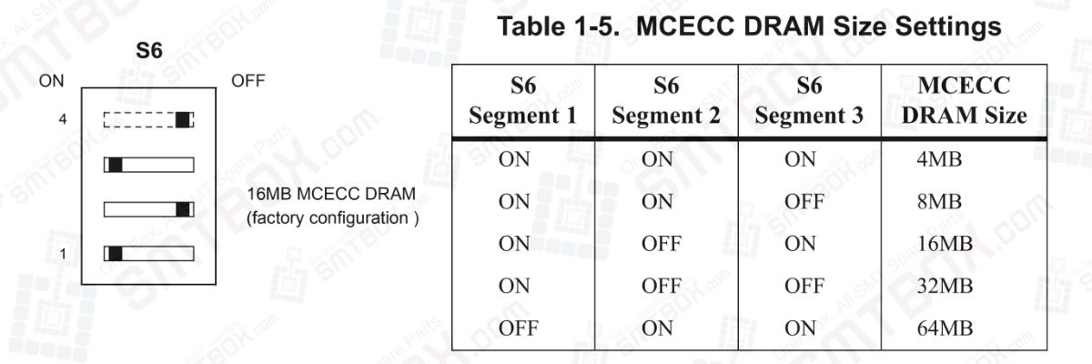
MVME1X2P4 boards use SDRAM (Synchronous DRAM) in place of DRAM. The MVME162P4’s 16/32MB shared SDRAM is configurable to emulate either of the following memory models: 1. 1MB, 4MB, 8MB, or 16MB shared parity-protected DRAM 2. 4MB, 8MB, 16MB, or 32MB ECC-protected DRAM The two memory controllers modeled in the Petra ASIC duplicate the functionality of… Continue reading about MCECC DRAM Size (S6) on Motorola MVME162P4 VME Embedded Controller

Segment 4 of switch S5 defines the Flash memory controller model (MC1 or MC2) to be emulated when enabling or disabling Flash memory accesses on the MVME162P4 board. With S5 segment 4 set to ON (the factory configuration), the board initializes in MC2 mode. With S5 segment 4 set to OFF, the board initializes in… Continue reading about Flash Write Enable Mode (S5 Pin 4) on Motorola MVME162P4 VME Embedded Controller
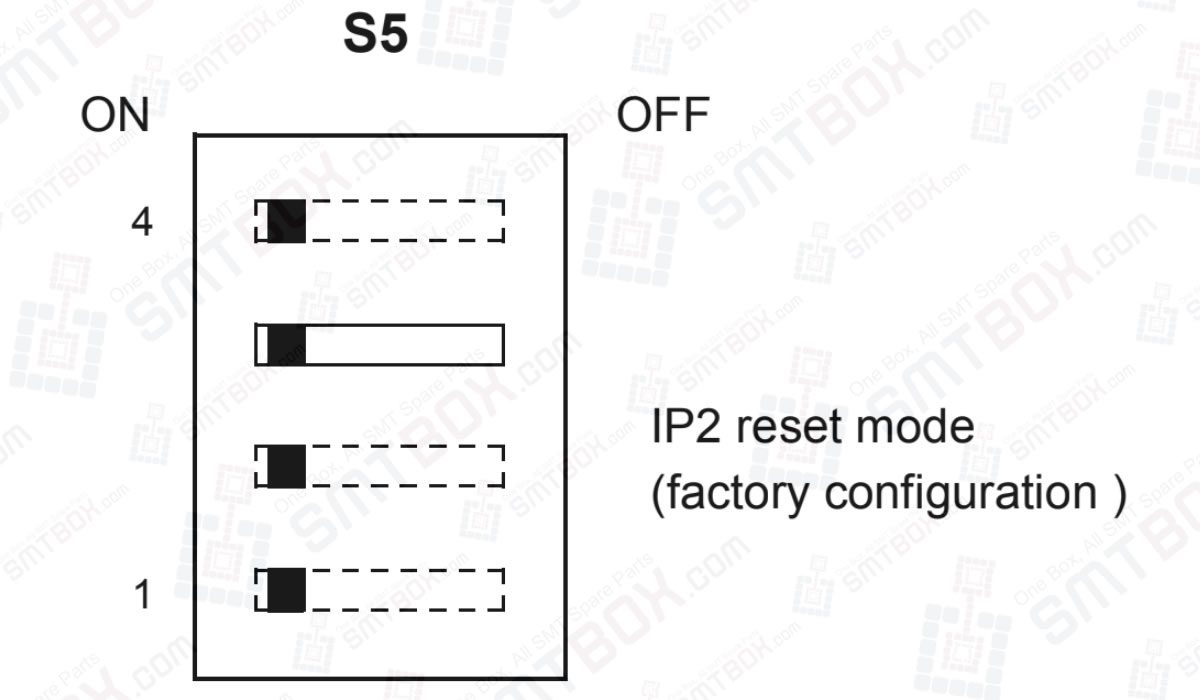
Segment 3 of switch S5 defines the IP controller model (IP1 or IP2) to be emulated when the board comes up. With S5 segment 3 set to ON (the factory configuration), the board initializes in IP2 mode. With S5 segment 3 set to OFF, the board initializes in IP1 mode. In IP2 mode, IP resets… Continue reading about IP Reset Mode (S5 Pin 3) on Motorola MVME162P4 VME Embedded Controller
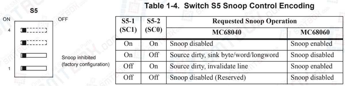
Segments 1 and 2 of switch S5 define the state of the snoop control bus when an IP DMA controller is local bus master. As shown in Table 1-4, S5 segment 1 controls Snoop Control signal 1 on the MC680x0 processor. S5 segment 2 controls Snoop Control signal 0. Setting a segment to ON produces… Continue reading about IP DMA Snoop Control (S5 Pins 1/2) on Motorola MVME162P4 VME Embedded Controller
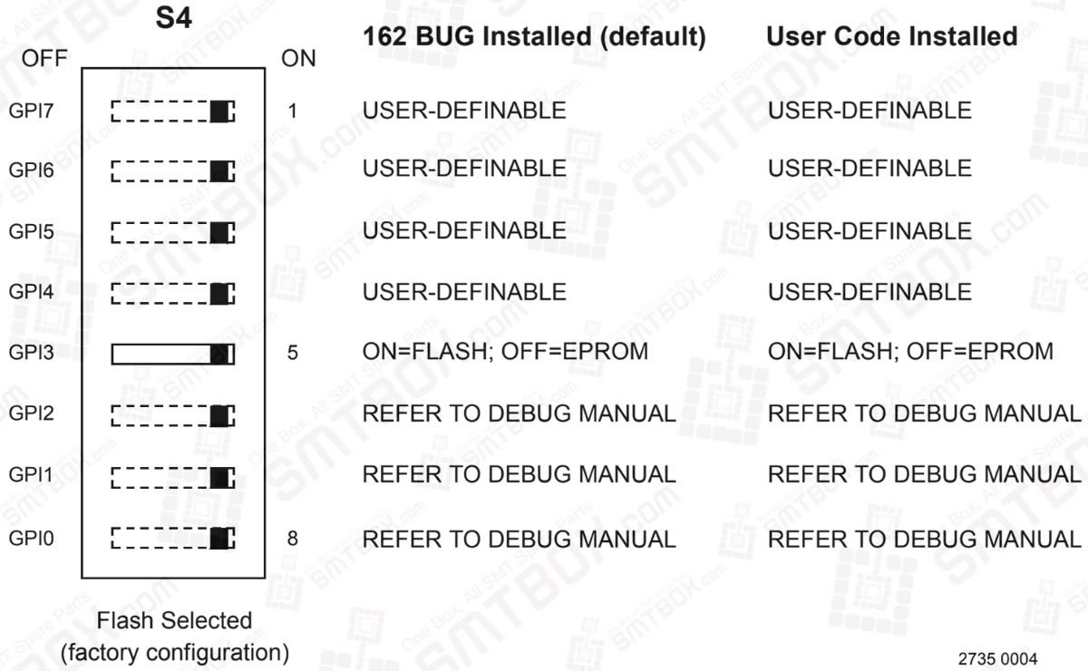
Switch S4 is similar in function to the general-purpose readable jumper headers found on earlier MVME162/172 series boards. S4 provides eight software-readable switch segments. These switches can be read as bits in a register (at address $FFF4202C) in the MC2 General-Purpose Inputs register in the Petra ASIC (refer to the Programmer’s Reference Guide for details)…. Continue reading about General-Purpose Readable Switch (S4 Pin 5) on Motorola MVME162P4 VME Embedded Controller
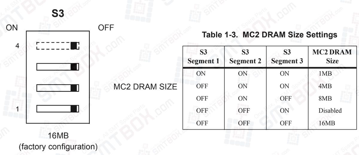
MVME1X2P4 boards use SDRAM (Synchronous DRAM) in place of DRAM. The MVME162P4’s 16/32MB shared SDRAM is configurable to emulate either of the following memory models: 1MB, 4MB, 8MB, or 16MB shared parity-protected DRAM 4MB, 8MB, 16MB, or 32MB ECC-protected DRAM The two memory controllers modeled in the Petra ASIC duplicate the functionality of the “parity… Continue reading about MC2 DRAM Size (S3) on Motorola MVME162P4 VME Embedded Controller

EPROM Size (J23) Header J23 selects the EPROM size. The MVME162P4 is factory-configured for a 4Mbit EPROM. Flash Write Protection (J24) When the Flash write-enable jumper is installed (factory configuration), Flash memory can be written to via the normal software routines. When the jumper is removed, Flash memory is not writable. Note: Model Number: MVME162P-344SE,… Continue reading about EPROM Size (J23) & Flash Write Protection (J24) on Motorola MVME162P4 VME Embedded Controller
1. Action: Check that air pressure drops down below the standard values. Error code: $2001 | Symptom and cause: Can’t move up the back up table (BUT). Backup table(BUT) fails to move up. Error code: $2002 | Symptom and cause: Can’t move down the back up table (BUT). Backup table(BUT) fails to move down. Error… Continue reading about Defined Fault On Module: Conveyor Part of Samsung CP40 Pick And Place Machine