Having issues with Installation Instructions on Motorola MVME162P4 VME Embedded Controller? Read our step-by-step SMT maintenance solution below. If you require replacement feeders, nozzles, or sensors, contact SMTBOX for OEM-compatible parts.
This section covers:
A. Installation of IndustryPacks (IPs) on the MVME162P4
B. Installation of the MVME162P4 in a VME chassis
C. System considerations relevant to the installation. Ensure that an EPROM device is installed as needed. Before installing IndustryPacks, ensure that the serial ports and all header jumpers and configuration switches are set as appropriate.
A.IP Installation on the MVME162P4
The MVME162P4 accommodates up to four IndustryPack (IP) modules. Install the IP modules on the MVME162P4 as follows:
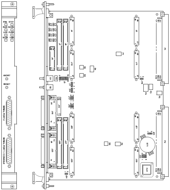
1. Each IP module has two 50-pin connectors that plug into two corresponding 50-pin connectors on the MVME162P4: J4/J5, J10/J11, J20/J21, J29/J30. See Figure 2-1 for the MVME162P4 connector locations.
– Orient the IP module(s) so that the tapered connector shells mate properly. Plug IP_a into connectors J4 and J5; plug IP_b into J10 and J11. Plug IP_c into J20 and J21; plug IP_d into J29 and J30. If a double-sized IP is used, plug IP_ab into J4, J5, J10, and J11; plug IP_cd into J20, J21, J29, and J30.
2. Four additional 50-pin connectors (J7, J8, J26, and J27) are provided behind the MVME162P4 front panel for external cabling connections to the IP modules. There is a one-to-one correspondence between the signals on the cabling connectors and the signals on the associated IP connectors (i.e., J8 has the same IP_a signals as J4; J7 has the same IP_b signals as J10; J27 has the same IP_c signals as J20; and J26 has the same IP_d signals as J29).
– Connect user-supplied 50-pin cables to J7, J8, J26, and J27 as needed. (Because of the varying requirements for each different kind of IP, Motorola does not supply these cables.)
– Bring the IP cables out the narrow slots in the MVME162P4 front panel and attach them to the appropriate external equipment, depending on the nature of the particular IP(s).
B. MVME162P4 Installation
With EPROM, SIM, and IP modules installed and headers or switches properly configured, proceed as follows to install the MVME162P4 in a VME chassis:
1. Turn all equipment power OFF and disconnect the power cable from the AC power source.
Inserting or removing modules while power is applied could result in damage to module components.
!Warning: Dangerous voltages, capable of causing death, are present in this equipment. Use extreme caution when handling, testing, and adjusting.
2. Remove the chassis cover as instructed in the user’s manual for the equipment.
3. Remove the filler panel from the card slot where you are going to install the MVME162P4.
– If you intend to use the MVME162P4 as system controller, it must occupy the leftmost card slot (slot 1). The system controller must be in slot 1 to correctly initiate the bus-grant daisy-chain and to ensure proper operation of the IACK daisy-chain driver.
– If you do not intend to use the MVME162P4 as system controller, it can occupy any unused double-height card slot.
4. Slide the MVME162P4 into the selected card slot. Be sure the module is seated properly in the P1 and P2 connectors on the backplane. Do not damage or bend connector pins.
5. Secure the MVME162P4 in the chassis with the screws provided, making good contact with the transverse mounting rails to minimize RF emissions.
6. Install the MVME712 series transition module in the front or the rear of the VME chassis. (To install an MVME712M, which has a double-wide front panel, you may need to shift other modules in the chassis.)
7. On the chassis backplane, remove the INTERRUPT ACKNOWLEDGE (IACK) and BUS GRANT (BG) jumpers from the header for the card slot occupied by the MVME162P4.
Note: Some VME backplanes (e.g., those used in Motorola “Modular Chassis” systems) have an autojumpering feature for automatic propagation of the IACK and BG signals. Step 7 does not apply to such backplane designs.
8. Connect the P2 Adapter Board or LCP2 Adapter Board and cable(s) to MVME162P4 backplane connector P2. This provides a connection point for terminals or other peripherals at the EIA-232-D serial ports, SCSI ports, and LAN Ethernet port. For information on installing the P2 or LCP2 Adapter Board and the MVME712 series transition module(s), refer to the corresponding user’s manuals (the Programmer’s Reference Guide provides some connection diagrams).
Note: If you intend to use the MVME162P4 with Port B in an EIA-530 configuration or an EIA-485/EIA-422 configuration, do not install the P2 or LCP2 Adapter Board and the MVME712 series transition module. They are incompatible with the EIA-530 interface and the EIA-485/EIA-422 interface.
9. Connect the appropriate cable(s) to the panel connectors for the serial ports, SCSI port, and LAN Ethernet port.
– Note that some cables are not provided with the MVME712 series transition module and must be made or purchased by the user. (Motorola recommends shielded cable for all peripheral connections to minimize radiation.)
10. Connect the peripheral(s) to the cable(s).
11. Install any other required VMEmodules in the system.
12. Replace the chassis cover.
13. Connect the power cable to the AC power source and turn the equipment power ON.
C. System Considerations
The MVME162P4 draws power from VMEbus backplane connectors P1 and P2. P2 is also used for the upper 16 bits of data in 32-bit transfers, and for the upper 8 address lines in extended addressing mode. The MVME162P4 may not operate properly without its main board connected to VMEbus backplane connectors P1 and P2.
Whether the MVME162P4 operates as a VMEbus master or VMEbus slave, it is configured for 32 bits of address and 32 bits of data (A32/D32). However, it handles A16 or A24 devices in the address ranges indicated in the VMEchip2 chapter of the Programmer’s Reference Guide. D8 and/or D16 devices in the system must be handled by the MC680x0/MC68LC0x0 software. For specifics, refer to the memory maps in the Programmer’s Reference Guide.
The MVME162P4 contains shared onboard DRAM whose base address is software-selectable. Both the onboard processor and offboard VMEbus devices see this local DRAM at base physical address $00000000, as programmed by the MVME162Bug firmware. This may be changed via software to any other base address. Refer to the Programmer’s Reference Guide for more information.
If the MVME162P4 tries to access offboard resources in a nonexistent location and is not system controller, and if the system does not have a global bus timeout, the MVME162P4 waits forever for the VMEbus cycle to complete. This will cause the system to lock up. There is only one situation in which the system might lack this global bus timeout: when the MVME162P4 is not the system controller and there is no global bus timeout elsewhere in the system.
Multiple MVME162P4s may be installed in a single VME chassis. In general, hardware multiprocessor features are supported.
Note: If you are installing multiple MVME162P4s in an MVME945 chassis, do not install an MVME162P4 in slot 12. The height of the IP modules may cause clearance difficulties in that slot position.
Other MPUs on the VMEbus can interrupt, disable, communicate with, and determine the operational status of the processor(s). One register of the GCSR (global control/status register) set in the VMEchip2 ASIC includes four bits that function as location monitors to allow one MVME162P4 processor to broadcast a signal to any other MVME162P4 processors. All eight registers of the GCSR set are accessible from any local processor as well as from the VMEbus.
The following circuits are protected by solid-state fuses that open during overload conditions and reset themselves once the overload is removed:
– IndustryPack +5V (F1, F6)
– Remote reset connector +5V (F2)
– LAN AUI +12V (F3)
– IndustryPack ±12V (F4, F5)
The FUSE LED illuminates to indicate that +12 Vdc is available. When an MVME712M module is used, the yellow DS1 LED on the MVME712M illuminates when LAN power is available, signifying that the fuse is good. If the Ethernet transceiver fails to operate, check fuse F3.
The MVME162P4 provides SCSI terminator power through a 1A fuse (F1) located on the P2 Adapter Board or LCP2 Adapter Board. If the fuse is blown, the SCSI device(s) may function erratically or not at all. When the P2 Adapter Board is used with an MVME712M and the SCSI bus is connected to the MVME712M, the green DS2 LED on the MVME712M front panel illuminates when SCSI terminator power is available. If the green DS2 LED flickers during SCSI bus operation, check P2 Adapter Board fuse F1.
If a solid-state fuse opens, you will need to remove power for several minutes to let the fuse reset to a closed or shorted condition.
Note: Model Number: MVME162P-344SE, Characteristics: 32MHz 68040, 16MB SDRAM, 2 SIO, 4 DMA IP, SCSI/Ethernet is used on Universal UIC HSP4797L Hitachi Sanyo TCM-X100 P.C.B. Mount 6300901030
Our editorial team consists of senior SREs, mechanical engineers, and SMT assembly specialists with over 15 years of industry experience in PCB assembly line optimization. All technical articles are reviewed and verified for mechanical and electronic compatibility before publication.