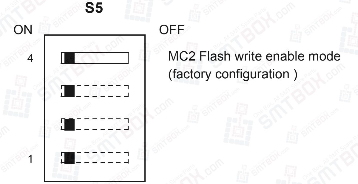
Segment 4 of switch S5 defines the Flash memory controller model (MC1 or MC2) to be emulated when enabling or disabling Flash memory accesses on the MVME162P4 board. With S5 segment 4 set to ON (the factory configuration), the board initializes in MC2 mode. With S5 segment 4 set to OFF, the board initializes in MC1 mode.
In MC2 mode, writes to Flash memory are enabled or inhibited by a control bit at memory location $FFF42042. With the control bit set to 1, Flash memory is write-enabled.
In MC1 mode, writes to Flash memory are enabled by a memory access to any location in the range $FFFCC000-$FFFCFFF. Writes to Flash memory are disabled by a memory access to any location in the range $FFFC8000-$FFFCBFFF. For details, refer to the Programmer’s Reference Guide listed in “Related Documentation” in Appendix E.
Note: Model Number: MVME162P-344SE, Characteristics: 32MHz 68040, 16MB SDRAM, 2 SIO, 4 DMA IP, SCSI/Ethernet is used on Universal UIC HSP4797L Hitachi Sanyo TCM-X100 P.C.B. Mount 6300901030
