Having issues with Yamaha Assembleon CLi Interface Control Board And Status Display? Read our step-by-step SMT maintenance solution below. If you require replacement feeders, nozzles, or sensors, contact SMTBOX for OEM-compatible parts.
The control board (reader control board assy) controls the ID reader boards. Up to 3 reader boards can be used with one control board. The control board also sends information obtained with the reader boards to the controller in the main machine (surface mounter).
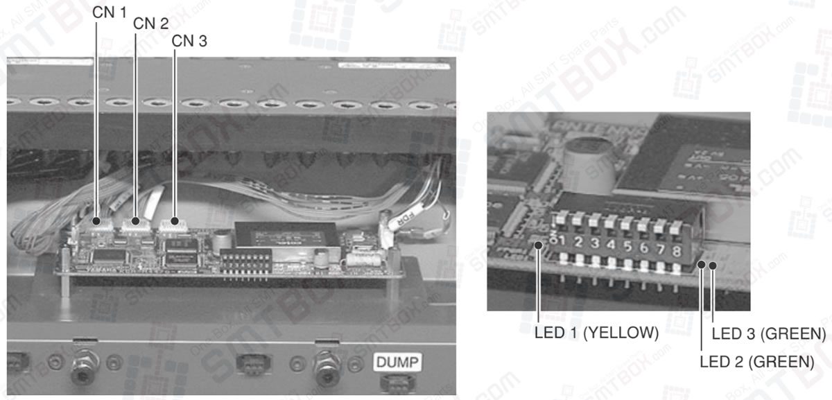
Hooking up the connectors
The wire harness from the ID reader boards should be hooked up to CN1 to CN3 on the control board. Use CN1 for smaller feeder set numbers. For example, when using a 20-feeder exchange carriage, the ID reader board for feeder set numbers 1 to 10 should be hooked up to CN1 and the ID reader board for feeder set numbers 11 to 20 to CN2. In this case, CN3 is left unused.
Status display LED
Status display LEDs are located on both sides of the DIP switch (S1) of the control board. You can view these LEDs through the check window (clear, plastic window) of the front cover. These LEDs indicate the following status.
LED display List
LED 1 YELLOW
Lighting pattern: Quick flashing Cycle: 250ms
Status: Communicating correctly with ID reader board.
Lighting pattern: Slow flashing Cycle: 3 sec.
Status: Not communicating correctly with ID reader board.
LED 2 GREEN
Lighting pattern: On
Status: Link established with mounter controller.
Lighting pattern: Off
Status: Link not established with mounter controller.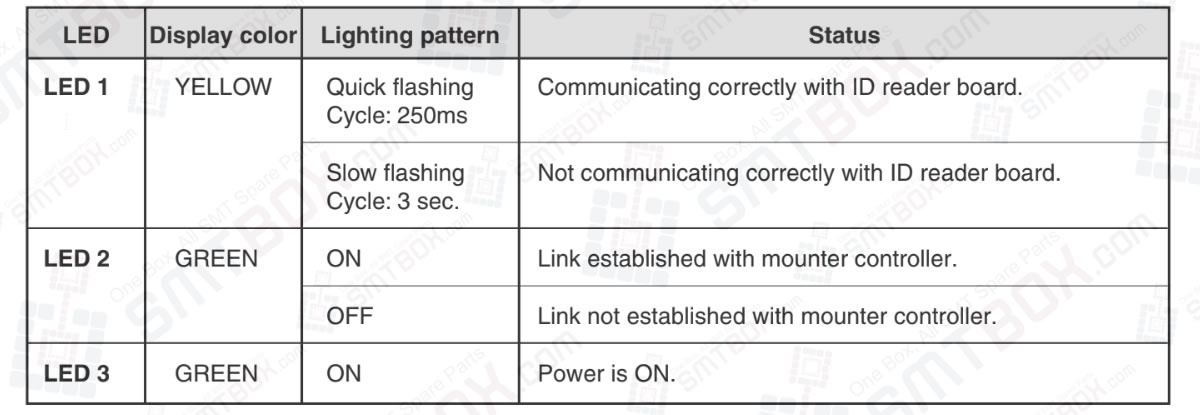
LED 3 GREEN
Lighting pattern: On
Status: Power is ON.
CAUTION: Make sure each reader board is connected correctly. If misconnected, the feeder position settings will be wrong and cause faulty operation.
NOTE: There are two types of ID reader boards: one for 10 feeders and one for 8 feeders. The ID reader board for 8 feeders is used for fixed feeder plates having 16, 24 or 32 feeder set positions.
Our editorial team consists of senior SREs, mechanical engineers, and SMT assembly specialists with over 15 years of industry experience in PCB assembly line optimization. All technical articles are reviewed and verified for mechanical and electronic compatibility before publication.