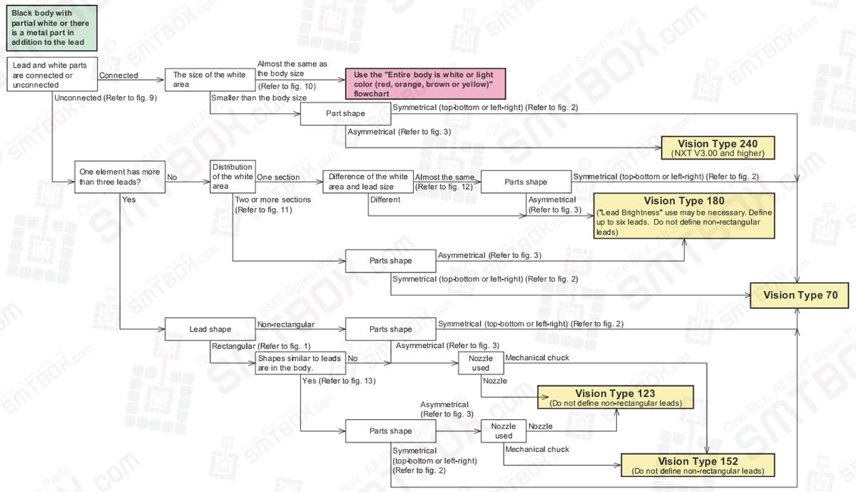
Case 3 for 4.6.3 Selecting A Vision Type Flowcharts (Leaded Parts) of Part Data Settings
Figure 1: Example of rectangular shaped leads and Example of non-rectangular shaped lead

The defined lead area and actual captured image is substantially different, distinguish by the rectangular and non-rectangular lead shapes.
For example, if the center thinner leadwidth is defined, a vision processing will occur when using vision type 180.
Figure 2: Example of left to right symmetrical part and Top to bottom symmetrical part

Determine the symmetry by considering all white items that can be seen (lead or other metal items).
Figure 3: Examples of asymmetrical parts
Determine the symmetry by considering all white items that can be seen (lead or other metal items)
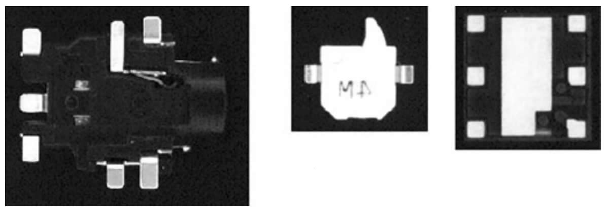
Figure 9: Leads are not connected to white areas

To determine whether or not the leads and white area are connected, observe the part and imagine how the lead will be seen by the parts camera.
Refer to the picture on the left. The gull-wing leads made shadows around the lead bases.
We see the leads and white area as being separated. The gold leads are bright and easily seen. The gull wing angle or lead width makes the lead base appear dark.
If VPDPlus and the camera stand are available, use that to acquire an image of the part. That is the easiest way to see how the machine will see the part.
Figure 10: For example, the size of the white area is nearly the same size as the body size.

The size, not the area.
Figure 11: Distribution of the white area. There are more than two sections of white area.

This part is like two three-pin minimolds facing each other in a white body.
The leads that must be detected are the two on each left and right side.
(The center lead has poor contrast so these leads should not be checked. )
However, the white area is not stable and there are some white blocks. These may be detected as leads and cause errors.
Figure 12: Example of when the white area and lead size are different and nearly same.

For these type of parts, the white area of the image can be different depending on the lot.
Therefore, the surface of the part may appear bright or dark in the image. In order to be able to correctly vision process in both cases, it is necessary to define three leads (the right top, left bottm and right bottom leads).
In a case of the bright parts, the center of the bright area can be detected as one big white area.
The center will not be wrongly detected because when this area and the lead sizes are compared, the sizes are completely different.
However, in a case of the dark parts, the vision processing system has problems determining the leads because there are approximately eight areas the same size and shape in the image.
Figure 13: Example of when lead-like shapes are in body of the part.