Case 1: Entire body color is black or a dark color (black, blue, green or yellow green)
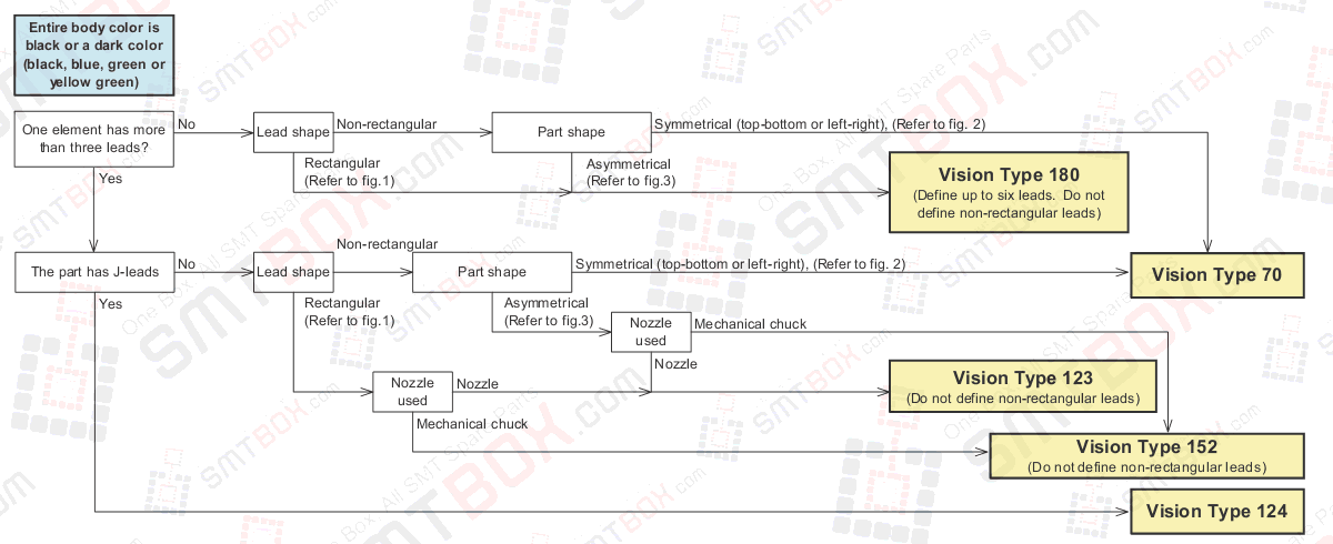
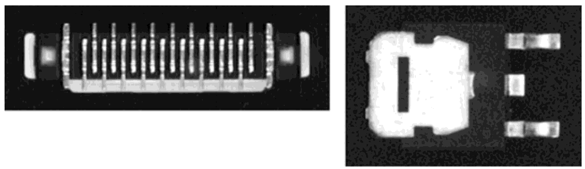
Figure 1: Example of rectangular shaped leads Example of non-rectangular shaped lead

The defined lead area and actual captured image is substantially different, distinguish by the rectangular and non-rectangular lead shapes.
For example, if the center thinner leadwidth is defined, a vision processing will occur when using vision type 180.
Figure 2 Example of left to right symmetrical part. Top to bottom symmetrical part
Determine the symmetry by considering all white items that can be seen (lead or other metal items)
Figure 3 Examples of asymmetrical parts
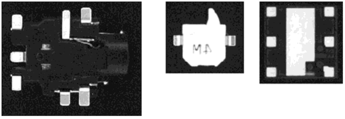
Determine the asymmetry by considering all white items that can be seen (lead or other metal items)