Having issues with Part Reference Point For Vision Type Details of Part Data Settings on FUJI NXT? Read our step-by-step SMT maintenance solution below. If you require replacement feeders, nozzles, or sensors, contact SMTBOX for OEM-compatible parts.
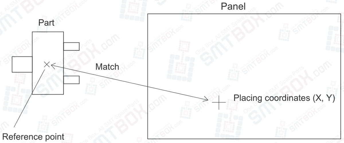
The part reference point is defined as the point on the part that is aligned with the placing coordinates on the panel when the part is placed.
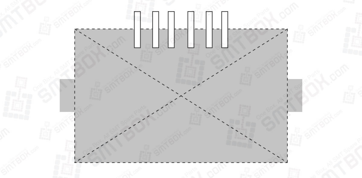
Body center
The center is taken from the outer-most points of the body; top, bottom, left, and right.
Part center
The part center is defined as follows.
The part center is taken from the outer-most points; top, bottom, left, and right.
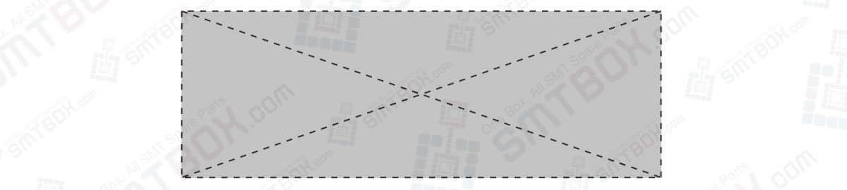
The part center is calculated from the coordinates of the lead ends or from the center coordinates of the ball grid taken from the outer-most points; top, bottom, left, and right.
The point of intersection of the center line from the outer-most points top to bottom and the center line from the outer-most points left to right yields the part center. However, if there are leads or a ball grid on only one side, a theoretical part center is defined based on the part data.
The following combinations are possible based on the lead positions.
The center moves depending on the lead positions, lead lengths, and lead widths.
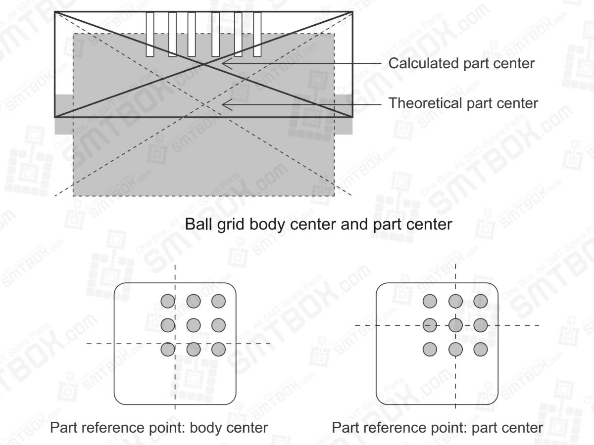
Note: If there are leads on three sides, the theoretical part center and the calculated part center will differ as shown in the following example.
For parts with leads on three sides, the part center is defined as the point of intersection of the center line from the outer-most points top to bottom and the center line from the outer-most points left to right. As a result, the part center required for placement differs from the actual placing position.

Our editorial team consists of senior SREs, mechanical engineers, and SMT assembly specialists focused on PCB assembly line optimization. All technical articles are reviewed and verified for mechanical and electronic compatibility before publication.