Having issues with P_Patterns Used For The NXT of P_pattern Details On FUJI NXT Scalable Placement Platform? Read our step-by-step SMT maintenance solution below. If you require replacement feeders, nozzles, or sensors, contact SMTBOX for OEM-compatible parts.
Definition: P_pattern Details
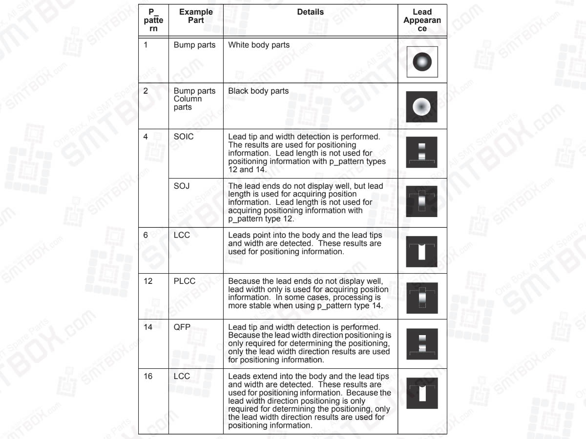
The p_pattern specifies the way the lead appears to the vision processing system and how the processing of the lead information for the part is to be performed. In addition, it is necessary to be aware that the placing position is affected by the specified p_pattern.
1. P_patterns used for the NXT
The following p_patterns are valid for use on the NXT with the frontlight system.
P_pattern: 1
Example Part: Bump parts
Details: White body parts
P_pattern: 2
Example Part: Bump parts Column parts
Details: Black body parts
P_pattern: 4
Example Part: SOIC
Details: Lead tip and width detection is performed. The results are used for positioning information. Lead length is not used for positioning information with p_pattern types 12 and 14.
P_pattern: 4
Example Part: SOJ
Details: The lead ends do not display well, but lead length is used for acquiring position information. Lead length is not used for acquiring positioning information with p_pattern type 12.
P_pattern: 6
Example Part: LCC
Details: Leads point into the body and the lead tips and width are detected. These results are used for positioning information.
P_pattern: 12
Example Part: PLCC
Details: Because the lead ends do not display well, lead width only is used for acquiring position information. In some cases, processing is more stable when using p_pattern type 14.
P_pattern: 14
Example Part: QFP
Details: Lead tip and width detection is performed. Because the lead width direction positioning is only required for determining the positioning, only the lead width direction results are used for positioning information.
P_pattern: 16
Example Part: LCC
Details: Leads extend into the body and the lead tips and width are detected. These results are used for positioning information. Because the lead width direction positioning is only required for determining the positioning, only the lead width direction results are used for positioning information.

Our editorial team consists of senior SREs, mechanical engineers, and SMT assembly specialists focused on PCB assembly line optimization. All technical articles are reviewed and verified for mechanical and electronic compatibility before publication.