Having issues with Introduction of How Polarity, Theta and Direction Affect Final Part Placement? Read our step-by-step SMT maintenance solution below. If you require replacement feeders, nozzles, or sensors, contact SMTBOX for OEM-compatible parts.
Written By Fuji Machine Manufacturing Co., Ltd. SMT Equipment Information Systems & Training
This document explains the affects of direction, polarity, and theta on final part placement in the two host systems, Fuji Flexa and FujiCam.
Direction and polarity are set in the part library (part number library if using relational mode in Fuji Flexa). In FujiCam, theta is set by several methods. The most common method for setting theta is to use the set theta command.
Refer to the FujiCam Programmerís Kit Reference Manual and online Help for information about specifying these settings. In Fuji Flexa, there is no need for the Theta command. The verify function is used to compare the rotation (and X/Y-position) of parts in Flexa to the CAD data.
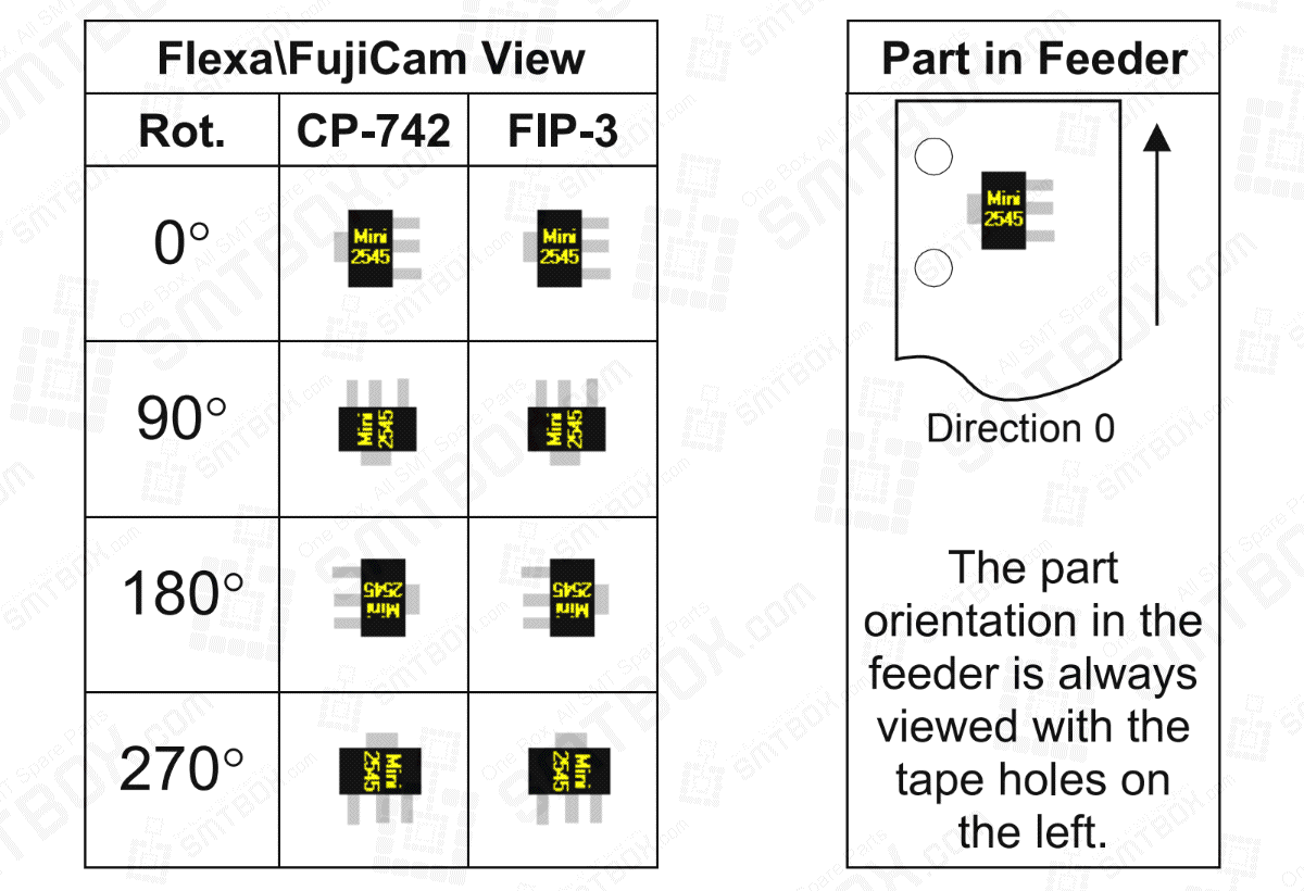
A placement of eight mini-molds is used throughout this document to clarify the affects of these settings. In the chart to the left, the mini-molds displayed are in the same orientation as that of the view. Two machines are placing four mini-molds at ninety degree intervals each. The orientation of the part in the feeder is displayed to the right of the view.
In the shape library (Fuji Flexa) \ Fuji Assembly Shape library (FujiCam), the mini-moldís orientation is:
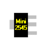
In this ocument, this orientation is referred to as the shape zero orientation.
The zero orientation for the shape from the CAD file is:
This is referred to as CAD zero orientation in this document.
This is the orientation of the part the CAD designer selected when the part is rotated zero degrees.
Note that changing direction, polarity, and theta does not alter the orientation of the parts in the Flexa\FujiCam views.
Our editorial team consists of senior SREs, mechanical engineers, and SMT assembly specialists with over 15 years of industry experience in PCB assembly line optimization. All technical articles are reviewed and verified for mechanical and electronic compatibility before publication.