
Having issues with How Theta Affects Final Part Placement by FUJI SMT Equipment Information Systems & Training? Read our step-by-step SMT maintenance solution below. If you require replacement feeders, nozzles, or sensors, contact SMTBOX for OEM-compatible parts.
The following example only applies to FujiCam, if using Fuji Flexa please read the section ìChecking CAD Zero Orientation in Fuji Flexa? found below.
In FujiCam
In this example, the three settings are:
Direction: 0
Polarized: Yes
Theta: 90° (Not used in Fuji Flexa)
The only setting that has changed from the previous example is that Theta for the parts is set to 90°.
In the table to the left, the actual part placement of the mini-molds by the two machines is shown with the completed panel in the same orientation as shown in the FujiCam view. As the table to the left displays, the final part placement does not match that of the FujiCam view.
Changing Theta for these mini-molds by 90 degrees altered the rotation. The basic formula for the new part rotation is: (part rotation) – (entered theta) = (new part rotation). For example, the first mini-mold rotation is 0. Using the formula (0 – 90 = 270), the new rotation for the first mini-mold is 270° which corresponds to the mini-mold rotated 270° degrees in the FujiCam view.
Changing Theta did not change the orientation of the parts in the FujiCam view. This is unlike changing the rotation of parts using the move part command which does alter the display of the parts.
Theta is used when the CAD zero orientation and the shape zero orientation do not match. If the CAD designer chose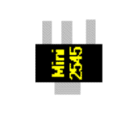
The shape zero orientation is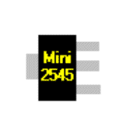
These two zero orientations do not match. If theta is not used to correct this problem, when a part is placed on the board with 0 rotation the part is placed on the panel as
the leads). To correct the CAD zero orientation, change the original CAD zero rotation from
In summary, Theta is only used for correcting differences between the CAD zero orientation and the shape zero orientation (from the Assembly Shape library). Theta changes the rotation of the parts but this change does not alter the display of the part.
Checking CAD Zero Orientation in Fuji Flexa
In Fuji Flexa, the shapes that are displayed in the view are from the shape library. Since these shapes are always based upon the data from the shape library, there never will be a discrepancy between the shape in the view and the shape zero orientation. However, a CAD operator can still use a CAD zero orientation that does not match the shape zero orientation. When this happens, the orientation of the shapes displayed in the view will not match that of the actual panel and can be spotted by an operator by comparing the view to an actual panel. This is because the shapes in the view are based on the shape library data, not the CAD data. The easiest and most error-free method of checking for this problem is to use the verify function if the outlines of the parts are available. Part outlines can be brought into the job from certain types of CAD files and\or Gerber data. If it is possible to specify the ìOutline? and ìLand? layers for the CAD type being imported, then the part outlines can be imported for that CAD data if these layers are specified. The part outlines are visual guides only to aide in the orientation of the parts, they do not affect vision data or any other part data settings. When using the verify function, the shape of the part from the shape library is displayed over the part outline from the CAD/Gerber file. The operator checks the position and orientation of the part to the part outline and if necessary, can change the rotation and position to match the part outline. This function actually changes the rotation of the part (and the orientation of the part shape in the view) so the orientation will match that of the CAD file and the panel. Direction is examined in the next example.
Our editorial team consists of senior SREs, mechanical engineers, and SMT assembly specialists with over 15 years of industry experience in PCB assembly line optimization. All technical articles are reviewed and verified for mechanical and electronic compatibility before publication.