Having issues with FlexJet Head Installation of UIC FlexJet Head Assembly 47541107 T47541107? Read our step-by-step SMT maintenance solution below. If you require replacement feeders, nozzles, or sensors, contact SMTBOX for OEM-compatible parts.
Install a FlexJet Head using the following procedure.
1. Move the beam(s) to a maintenance position using Manual Control.
2. Place the machine in the powered down mode. Then execute your site’s Lockout/Tagout procedure.
3. Use ESD precautionary measures and configure the Head Control Asm PC BD according to the Maintenance Support Document, PC Jumper Config., SMT document.
4. Carefully place the FlexJet Head on the head mounting plate so the mounting plate dowel pins align with and enter the alignment holes of the head. Verify that the FlexJet Head is flush against the head mounting plate.
5. Apply Loctite 222 and torque the 2 set screws in the head mounting bracket, on the left side of the FlexJet Head, to 2.5 in-pounds (0,282 Nm) and tighten the nuts on set screws.
6. Apply Loctite 222 and torque the main head retaining bolts on both the right and left side of the FlexJet Head to 84 in-pounds (9,49 Nm).
7. Connect pneumatic line 9 to the FlexJet Head input pneumatic connector.
8. Connect the HD INTF2 (Power) Cable Assembly to the head first.
9. Connect the HD INTF1 Cable Assembly and CAM INTF Cable Assembly.
10. Disconnect the 3 video connectors on the IGUS Cable from PEC Box. Connect the 3 video connectors on CAM INTF Cable Assembly to the appropriate video connectors on IGUS Cable. Refer to the following illustration and table.
CAM INTF Cable Assembly = C.I.C.A.
IGUS Cable = I.C.
C.I.C.A.: INTF.V-OUT | I.C.: PEC1.V-OUT
C.I.C.A.: Pec1.V-DRIVE | I.C.: Pec1.V-DRIVE
C.I.C.A.: Pec1.H-DRIVE | I.C.: Pec1.H-DRIVE
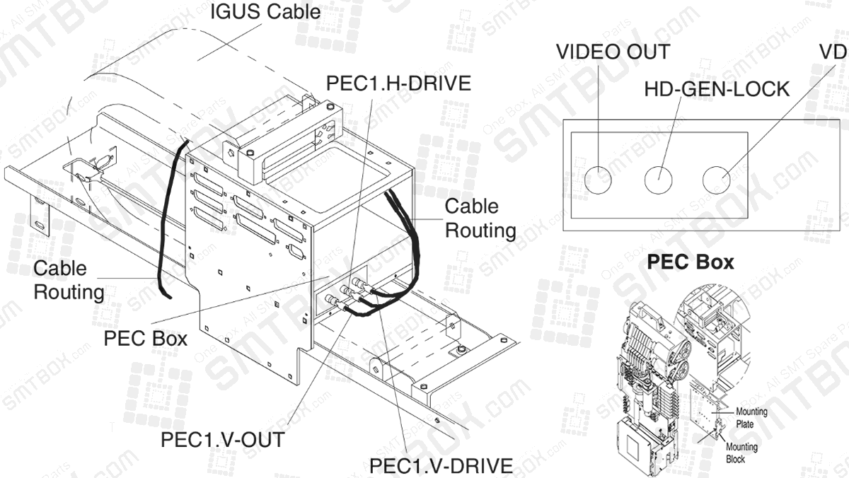
11. Connect the 3 video connectors on CAM INTF Cable Assembly to the appropriate video connectors on the PEC box. Refer to the following table.
CAM INTF Cable Assembly = C.I.C.A.
PEC box = P.B.
C.I.C.A.: Pec1.V-OUT | P.B.: Video Out
C.I.C.A.: Pec1.V-DRIVE | P.B.: VD
C.I.C.A.: Pec1.H-DRIVE | P.B.: HD-GEN-LOCK
12. If necessary, remove the 2 screws securing the handle to the Z-Axis Index Housing Assembly. Then remove the handle. Refer to the illustration to the left.
13. Install the FlexJet Head Cover.
14. Calibrate the FlexJet Head. Refer to the Calibration, CPE and Measurement manual.
15. Verify that any covers previously removed are installed, such as the safety cover below the hinged cover.
Procedures and Adjustments: The following subsections contain the maintenance procedures that are required for proper FlexJet Head Assembly operation.
Our editorial team consists of senior SREs, mechanical engineers, and SMT assembly specialists with over 15 years of industry experience in PCB assembly line optimization. All technical articles are reviewed and verified for mechanical and electronic compatibility before publication.