Having issues with Coupler Body Assembly Replacement / Alignment on UIC FlexJet Head Assembly 47541107 T47541107? Read our step-by-step SMT maintenance solution below. If you require replacement feeders, nozzles, or sensors, contact SMTBOX for OEM-compatible parts.
Replace or align a Coupler Body Assembly using the following procedure.
1. Park the FlexJet Head Assembly at a maintenance position.
2. Place the machine in the powered down mode. Then execute your site’s Lockout/Tagout procedure.
3. Open the hinged machine cover to access the FlexJet Head. Then remove the safety cover below the hinged cover.
4. Remove the FlexJet Head cover.
5. Remove the FlexJet Head. Refer to the FlexJet Head Removal procedure located in this document.
6. Remove the Camera assembly from the FlexJet Head. Refer to the OTH Camera Assembly Removal procedure located in the Camera Asm, 2.6 OTH document.
7. Remove the nozzles from Coupler Body Assembly by using to the Installation/Removal of Nozzle procedure located in the FlexJet Spindle Assembly document.
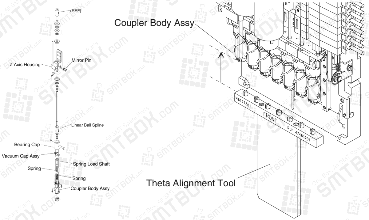
8. Remove the damaged Coupler Body Assembly from the Bearing Cap by removing the 2 mounting screws and disconnecting the 2 Tubings. Refer to the following illustration.
9. Install the new Coupler Body Assembly, but do not tighten the 2 mounting screws.
10. Manually position the Theta Alignment Tool from the FlexJet Tool Kit under the FlexJet head. Align and insert the tool into Coupler Body Assemblies. Refer to the following illustration.
11. Tighten the 2 mounting screws for the new Coupler Body Assembly to the specified torque with the tool installed.
12. Remove the Theta Alignment Tool.
13. Connect the 2 Tubings to the Coupler Body Assembly.
14. Install the Camera assembly. Refer to the OTH Camera Assembly Installation procedure located in the Camera Asm, 2.6 OTH document.
15. Install the FlexJet Head. Refer to the FlexJet Head Installation procedure located in this document.
16. Install the nozzles that were removed. Then verify that the nozzle configuration is correct in Universal Platform Software.
17. Verify FlexJet Head vacuum levels. Refer to Vacuum Level Verification section located in this document.
18. Install the FlexJet cover.
19. Perform Calibration. Refer to the Calibration, CPE and Measurement manual.
20. Record on the appropriate copied sheet from the Maintenance Log document that this procedure was performed and include the date.
Note: The tool must be removed from the Coupler Body Assemblies before head use to prevent head damage.
Our editorial team consists of senior SREs, mechanical engineers, and SMT assembly specialists with over 15 years of industry experience in PCB assembly line optimization. All technical articles are reviewed and verified for mechanical and electronic compatibility before publication.