(1) Axis Control: X/Y/Z/R/S axes, Semi-closed loop control with AC servomotors
(2) Position Control: Absolute method
(3) Data Input Increment: X/Y/Z/S 0.01 mm or 0.1 mil Rotation 0.01 degree
(4) Data Input Method: Manual, teaching, offline programming
(5) Memory Capacity: Max. 3000 steps per program, Max. 500 programs in the built-in hard disk
(6) External Memory: 3.5″ floppy disk 1 unit Hard disk 1 unit
(7) Display: One 15″ color CRT for operation and vision monitoring
English, Chinese, Korean, or Japanese / mm or inch
(8) Operation: Mouse, mini keyboard, operation switches
(9) Ethernet: Network standard IEEE802.3 Ethernet
Interface port RJ-45
Applicable network 10BASE-T
Data transfer rate 10Mbps.
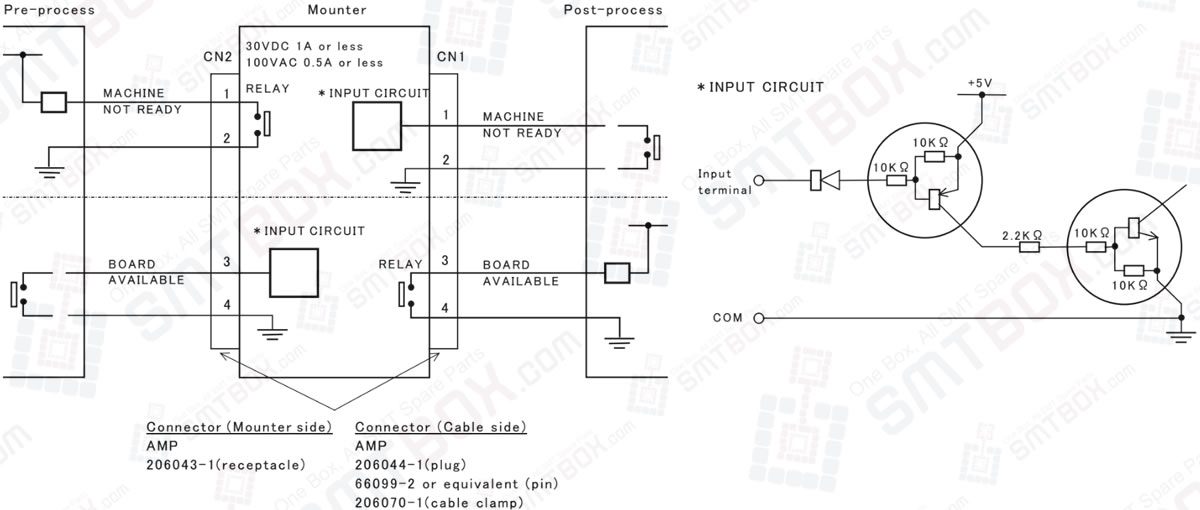
(10) Up and Downstream Signals
Pre-process signal: Output by contact
Post-process signal: Output by current
i-PULSE Interface: Upper half of the diagram below
SMEMA Interface: Whole diagram below.
