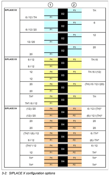
Legend
1. Placement area 1
2. Placement area 2
Placement heads
– 6 = C&P6 head
– 12 = C&P12 head
– 20 = C&P20 head
– TH = Twin head

Two placement head variants are used:
The placement system is based on a torsionally rigid and vibration dampened machine frame made of cast steel. The placement system has either two (X2), three (X3) or four (X4) gantries. These can be positioned independently of one another in the X and Y directions, by fast and accurate linear motors. Each gantry is equipped with a placement head.
The head modularity principle developed by Siemens allows you to change placement heads quickly and easily.
Four locations are available for supplying the components. A maximum of four component trolleys or two Matrix Tray Changers (MTC) can be used.
A new generation of feeders and new component trolleys have been introduced for the SIPLACE X-Series and the C&P20 head. A mixture of “old” component trolleys (S feeders) and “new” component trolleys (X feeders) is possible in the same placement area. In this case, the C&P would only use new generation feeders.
The placement heads pick the components from the fixed conveyor on the component trolley or from the MTC trays and place the boards waiting. Each SIPLACE X placement head has its own processing area: