Use this to check and edit the pitch, X-, Y-, and Z-positions for picking parts in feeders.
Starting the pickup test.
1. Transmit the job with the pickup positions to be tested to the machine and wait for the main screen to display on all of the operation panels for the modules.
2. Start MEdit and log on if necessary.
3. Click [Open Current Job] from the [File] menu. The [Acquire current production job] dialog box displays.
4. Select the line with the machine for the pickup positions to be tested in the left pane and then select machine in the right pane. The name of the selected job is automatically displayed in the [Job Name] dialog box.
5. Specify the module from which to test the tray pickup position data.
6. Select the [Feeder Setup] tab.
7. Select the slot for which the pickup test is to be performed.
8. Select [Pickup Check] from the [Tool] menu. The background color of the operation panel for the module in question turns violet to indicate that that module is in a test mode. There are several conditions in which the module cannot be changed to this mode and an error occurs.
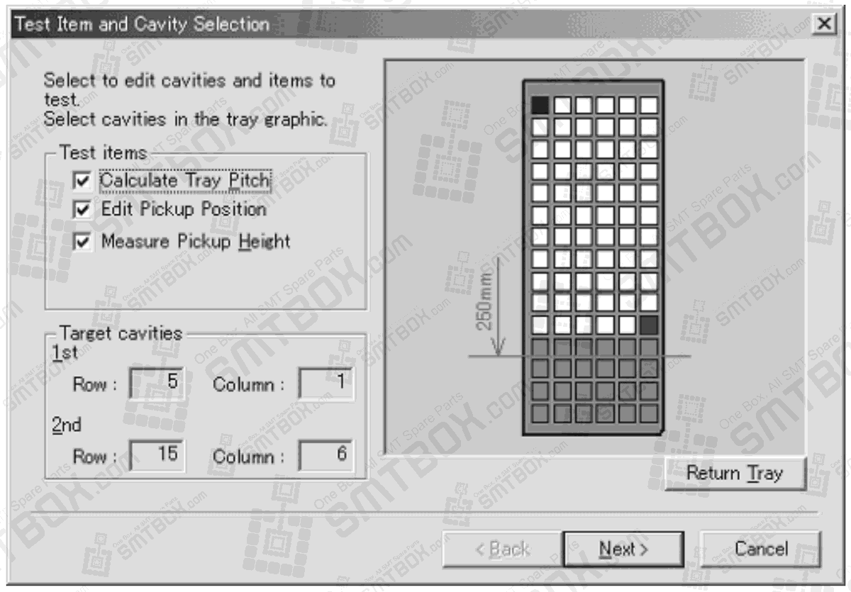
9. Select the type of tests which are to be performed in the dialog box that is displayed. If the [Calculate Tray Pitch] or [Edit Pickup Position] options are selected, proceed to the next step. If the [Measure Pickup Height] option only is selected, then go to step 18.
Note: Because the pickup height measurement uses pickup pressure control, the height measurement test is not possible using heads which have no pressure check sensor. In such cases, the “Measure pickup Height” item cannot be selected. Only the H01 and FO4 heads can be used to perform this test.
Checking and editing the tray pitch and X- and Y-positions.
10.If the [Calculate Tray Pitch] option is selected, then specify two possible pick positions in the tray. If the [Edit Pickup Position] is only selected, then select only one pickup position. [Next] is not available until the required positions have been selected.
Note: It is not necessary to select the first and last pickup positions. Any position in the tray can be selected. However, if measuring the tray pitch, the measured results will be better if the two selected cavities are the furtherest from each other. Tray positions past the top 250 mm of the tray cannot be selected due to restrictions in the travel range of the mark camera.
11.Click [Next] and the [Edit First Cavity] step is displayed.
12.Click [Acquire] to take a picture of the part in the first specified slot in the tray. A picture of the part is taken and displayed.
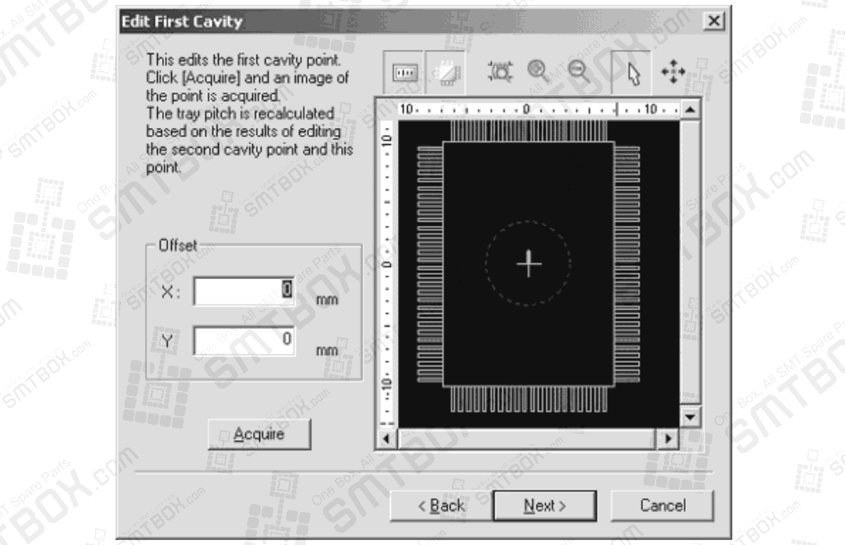
13.Check the pickup position in the X- and Y-direction using the displayed image. If the pickup position needs to be moved, click the positioning button (the button with the four arrows) and then click in the image of the graphic at which the pickup should be performed (the [Offset] values are automatically changed).
14.When the pickup position for the part is correct, click [Next]. If the tray pitch test is not being performed, then go to step 18.
15.The step for the second specified cavity is displayed (if tray pitch is being measured). Click [Acquire] to take a picture of the part in the second specified slot in the tray. A picture of the part is taken and displayed.
16.Check the second pickup position in the X- and Y-direction using the displayed image. If the pickup position needs to be moved, click the positioning button (the button with the four arrows) and then click in the image of the graphic at which the pickup should be performed (the [Offset] values are automatically changed).
17.When the pickup position for the part is correct, click [Next]. If the pickup height test is not being performed, go to step 24.
Checking and editing the pickup height for a tray.
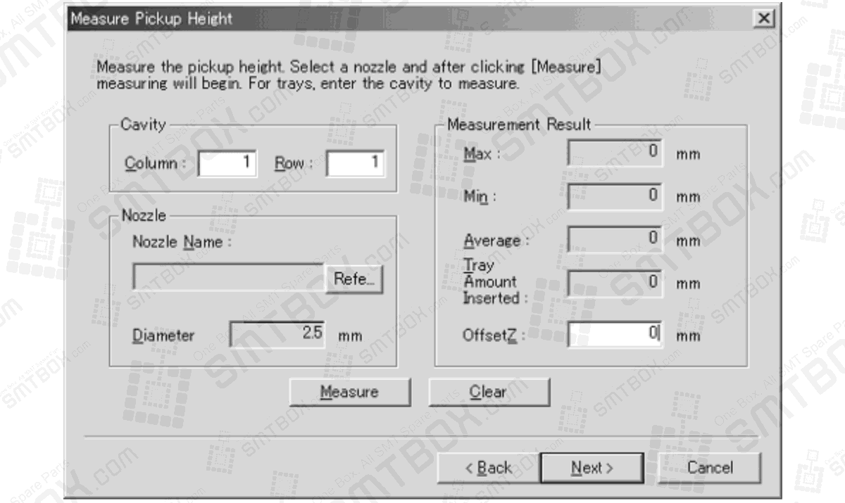
18.The [Measure Pickup Height] step is displayed. Specify the cavity position on which to perform the pickup test (a part must be present in the cavity) in the [Cavity] group.
Note: Trays have a certain amount of warp. Therefore, the measurement should be performed at multiple cavities to determine the optimum pickup height. (Fuji recommends measuring the center cavity and the 4 corner cavities.)
19.Click [Ref.] to specify which nozzle to use for the test.
Note: The machine knows which nozzles are present in the module (if a check has been performed by the machine). In cases where the job-specified nozzle can be used for the height measurement, that nozzle is automatically selected.

20.Select the nozzle to be used for the measurement in the dialog box that is displayed and then click [OK].
Note: If the module has not yet performed calibration and does not know what nozzles are present in the nozzle station, click [Measure] to have the module check which nozzles are present.
21.Click [Measure] to begin the pickup height test.

22.The results of the test are displayed and the Z offset is automatically determined. It is possible to manually edit this value.
Note: A dialog box is displayed when a stroke error occurs. Click [Yes] in this dialog box to try moving the head down an extra 1 mm and measure again. The same error occurs if there is no part in the pickup position. If unsure if a part is present or not, check the part status in the feeder.
23.Once the Z offset has been determined and the results are acceptable, click [Next].
Sending changes back to the module.
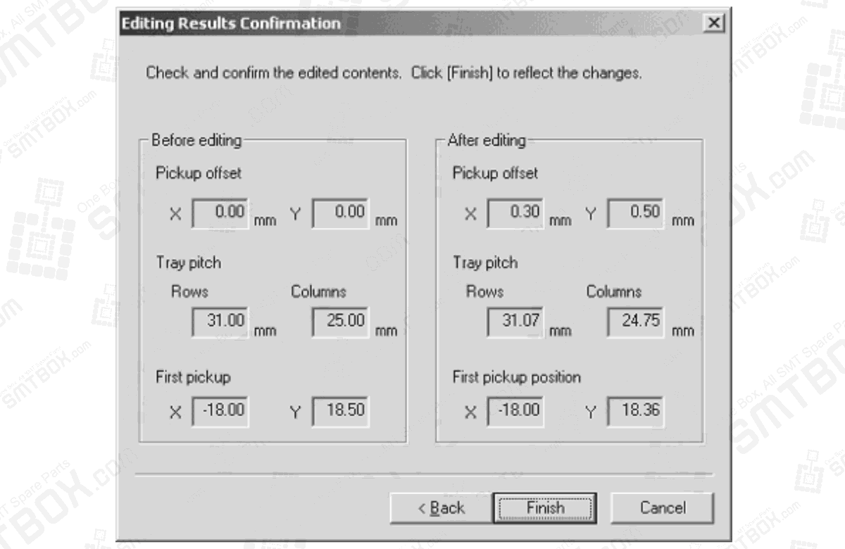
24.The offset and pitch results for the pickup position test are displayed. Check the results and if the results are acceptable, click [Finish]. It is possible to click [Back] to return to previous steps of the pickup test.
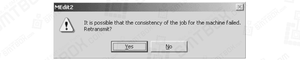
25.A dialog box is displayed asking if the results should be sent back to the module. Click [Yes] to send the new offset data back to the module.
26.A dialog box is displayed asking if Data Checker should be run or not. Click [Yes] to check the job data with data checker.
27.Select the modules to which to sent the changes to the job data back and then click [OK].
Note that is the same part is present in multiple modules, that it is important to select all of the modules that have the same part.