1. Preparations
(1) Rotate the guide clockwise until it will turn no further and then turn it counter-clockwise by one revolution.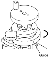

(2) Raise the spindle by rotating it counter-clockwise. Then raise and rotate the stopper ring clockwise to check that the spindle has been raised sufficiently.

(3) Rotate the stopper counter-clockwise to lower it so that it rests on the guide.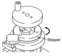
2. Setting the Nozzle Holder on the Jig
Depending on machine type, the bracket is position in one of the following two ways.
(1) For CP-6 series nozzle holders.
Position the bracket as indicated in the figure below.
Then insert the nozzle holder as indicated and lock it into position by turning the locking knob.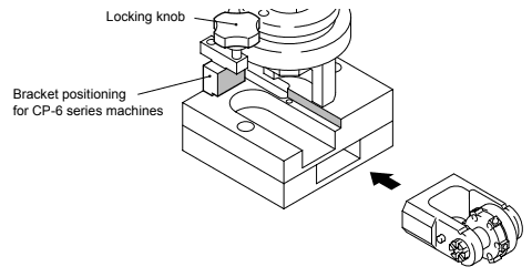

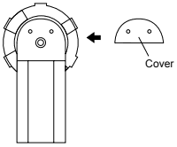
(2) For CP-65 series nozzle holders.
Position the bracket as indicated in the figure below.
Remove the two M2CS bolts from the nozzle holder and remove the cover. Rotate the nozzle holder until nozzle insertion hole No. 3 faces upwards to avoid interference between the dog and the guide. Then insert the nozzle holder as indicated and lock it into position by turning the locking-knob.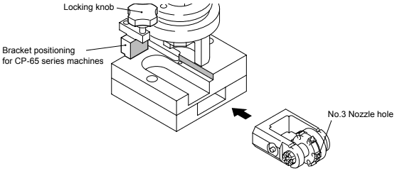

3. Removing the Needle Pin
(1) Rotate the guide clockwise until it will turn no further.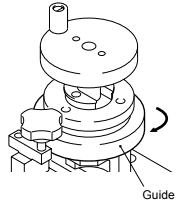

(2) Remove the needle pin by rotating the spindle clockwise until it will turn no further and collect the needle pin from the cavity at the bottom of the jig.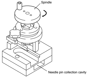

4. Removing the Nozzle Holder from the Jig
(1) Raise the spindle by rotating it counter clockwise. Then raise and rotate the stopper ring to check that the spindle has been raised sufficiently.
(2) Rotate the guide counter clockwise by one revolution so that the nozzle holder can be removed without any interference.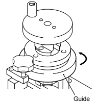

(3) Loosen the locking knob and remove the nozzle holder from the jig.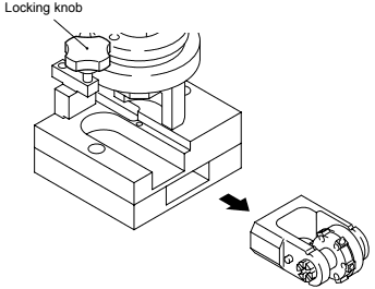

5. Disassembling the Nozzle Holder
(1) Insert a 3 mm CS bolt in the tapped end of the nozzle holder’s axis.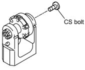

(2) Use the inserted bolt to remove the axis from the holder.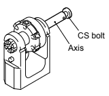

(3) Remove the two 2 mm bolts by which the dog is secured.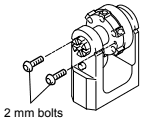

(4) Remove the spring set (dog, collars, spring, bearing and washer) from the holder.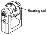

(5) Finally, remove the rotor from the holder.
6. Cleaning the Parts
Note: When cleaning more than one nozzle holder at the same time, be sure to keep the parts for each nozzle holder together. Assembling nozzle holders from different parts may result in damage.
(1) Clean the axis, needle pin and collars in methylene chloride. After cleaning use a blow dryer to dry the parts.
(2) Use an ultrasonic cleaning devise filled with methylene chloride to clean the rotor for five minutes. After cleaning use a blow dryer to dry the parts.
(3) Clean the shafts in the holder using a soft cloth drenched in methylene chloride. After cleaning use a blow dryer to dry the parts.
7. Reassembling the Nozzle Holder
Note: When assembling more than one nozzle holder at the same time, be sure to keep the parts for each nozzle holder together. Assembling nozzle holders from different parts may result in damage.
(1) Apply Daphne Eponex No. 2 grease to the area indicated in the figure below.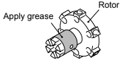

(2) Insert the the rotor in the shaft of the holder.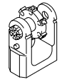

(3) Reassemble the spring set (dog, collars, spring, bearing and washer), and insert it between the rotor and the opposite arm of the holder.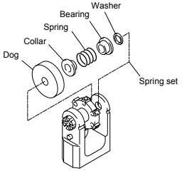

(4) Use the centring pin to align all parts.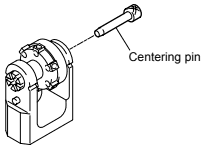

(5) Depending on the machine type,
CP-6: Rotate the dog until the Fuji logo on the rotor falls between number 1 and 2 on the dog, and secure the dog with the two 2 mm bolts.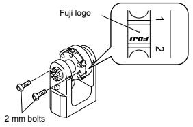

CP-65: Rotate the rotor until nozzle insertion hole No. 3 faces upward and rotate the dog so that the abrasive section is positioned as shown in the figure below.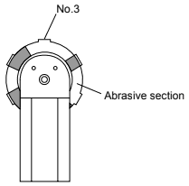

(6) Finally, grease the nozzle holder axis, remove the centring pin, and insert the axis so that the hole at the tip is aligned with the needle pin hole in the nozzle holder arm.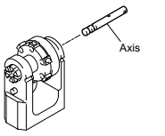

8. Reinserting the Needle Pin
(1) Use a thin brush to apply adhesive (Threebond 1373B) to the needle pin hole on the nozzle holder arm.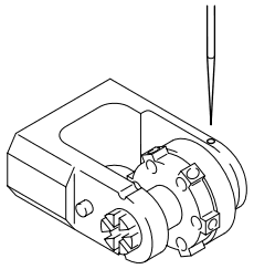

(2) Rotate the guide clockwise until it will turn no further and turn it counter-clockwise by one revolution. Then insert the nozzle holder and lock it into position by turning the locking-knob.

(3) Raise the spindle by rotating it counter-clockwise. Then raise and rotate the stopper ring clockwise until it can be rotated no further.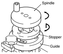

(4 ) Rotate the guide clockwise until it will turn no further. Then reinsert the needle pin by rotating the spindle clockwise until it touches the raised stopper.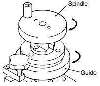

9. Removing the Nozzle Holder from the Jig
(1) Raise the spindle by rotating it counter clockwise. Then rotate the guide counter clockwise by one revolution so that the nozzle holder can be removed without any interference.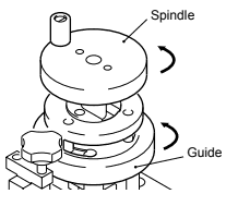

(2) Loosen the locking knob and remove the nozzle holder from the jig.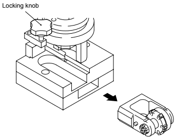

(3) Remove excess adhesive.
(4) Reattach the cover for CP-65 nozzle holders.